JAPANESE / ENGLISH
JAPANESE / ENGLISH
Last updated on 03/26/2025
With the growing importance of AI and cloud computing, demand for energy-efficient data center interconnect is increasing rapidly. Connecting data centers with O-band optics reduces power consumption arising from dispersion compensation, as the standard single-mode fiber shows its zero dispersion in the O-band. Now the O-band is the primary wavelength for high-speed ethernet, co-packaged optics, optical I/O for AI, High Performance Computing (HPC) and disaggregated computing.
These applications typically use WDM transmission in the O-band, and several WDM grids are defined as industry standards, for example, CWDM4, LAN-WDM4, LAN-WDM8, CW-WDM (18-nm and 36-nm span). O-band optical amplifiers are key to this O-band WDM ecosystem, as they allow simultaneous amplification of the WDM signal.
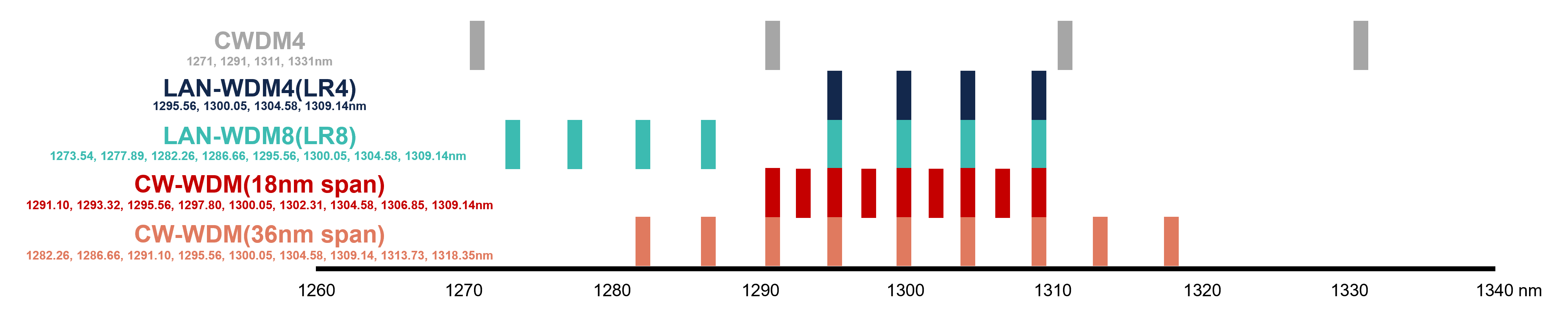
Figure 1: Center wavelength of grids for CWDM4, LAN-WDM4, LAN-WDM8 and CW-WDM.
In this blog, we present two types of flagship fiber amplifier models that we will be launching this year – Praseodymium-doped fiber amplifier (PDFA) and Bismuth-doped fiber amplifier (BDFA). We show, with experimental results, the pros and cons of these two products for WDM amplification. This result will be one guideline on how to choose an appropriate amplifier model depending on the WDM grid of interest.
Our new model of PDFA (AMP-FL8612-OB-27) can deliver more than 27-dBm output power from a 0-dBm input signal light, which is the highest output power among commercially available fiber amplifiers in the O-band. The output power of our new BDFA (AMP-FL8621-OB-19) is 19 dBm with the input power of 0 dBm. Although the output power is lower than that of the PDFA, it can amplify a wider wavelength bandwidth.
We have manufactured demo units for these two models for both internal and customer evaluation. Preliminary data sheets can be downloaded from the link below.
Our evaluation of these two demo units was conducted by the amplification of WDM signals. Two types of input signal patterns, LR8 (0 dBm/ch) and CW-WDM (36-nm span, 8+1 ch, 0 dBm/ch), are used for amplification test of the PDFA and BDFA. The schematic diagram of the experimental setup is depicted in Fig.2, and the output spectra of these fiber amplifiers with the LR8 and CW-WDM input signals are shown in Fig.3 and Fig.4, respectively.
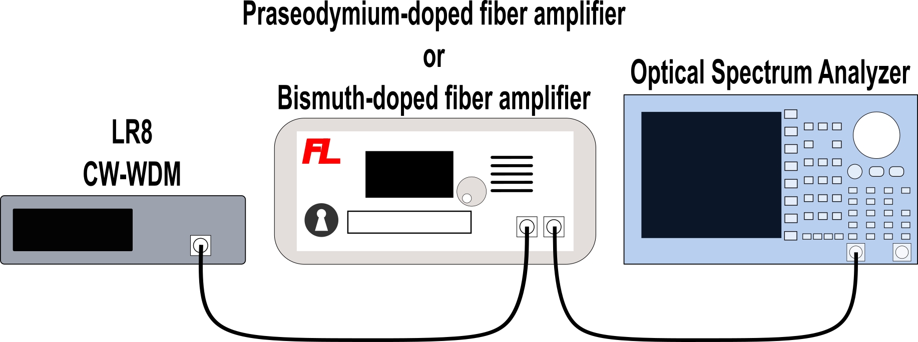
Figure 2: Schematic diagram of the experimental setup for amplification of LR8 and CW-WDM signal by using PDFA and BDFA.
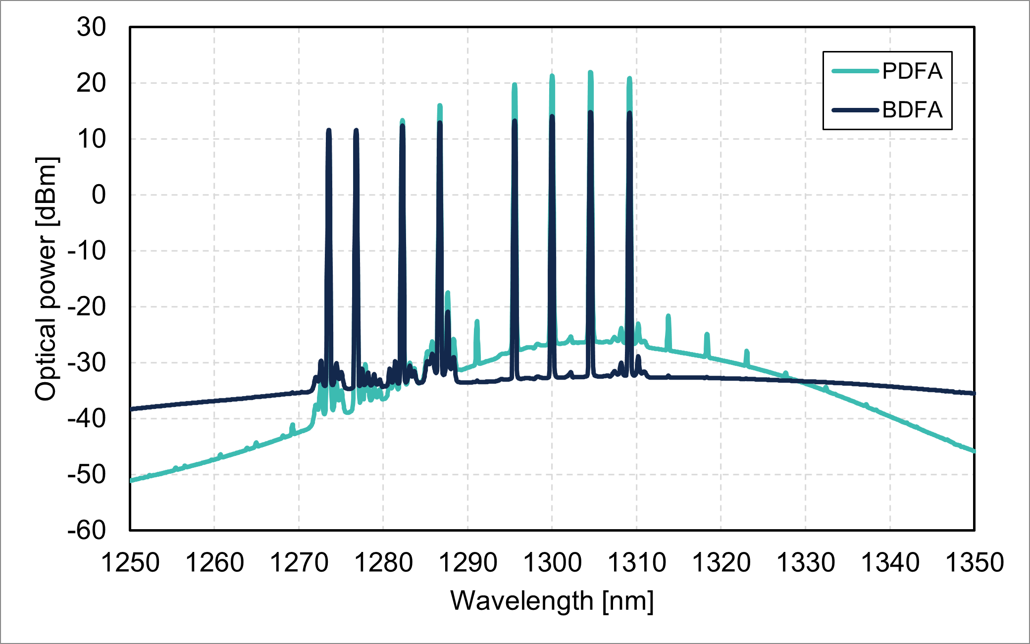
Figure 3: Output spectra from PDFA and BDFA with the 0-dBm input signal of LR8.
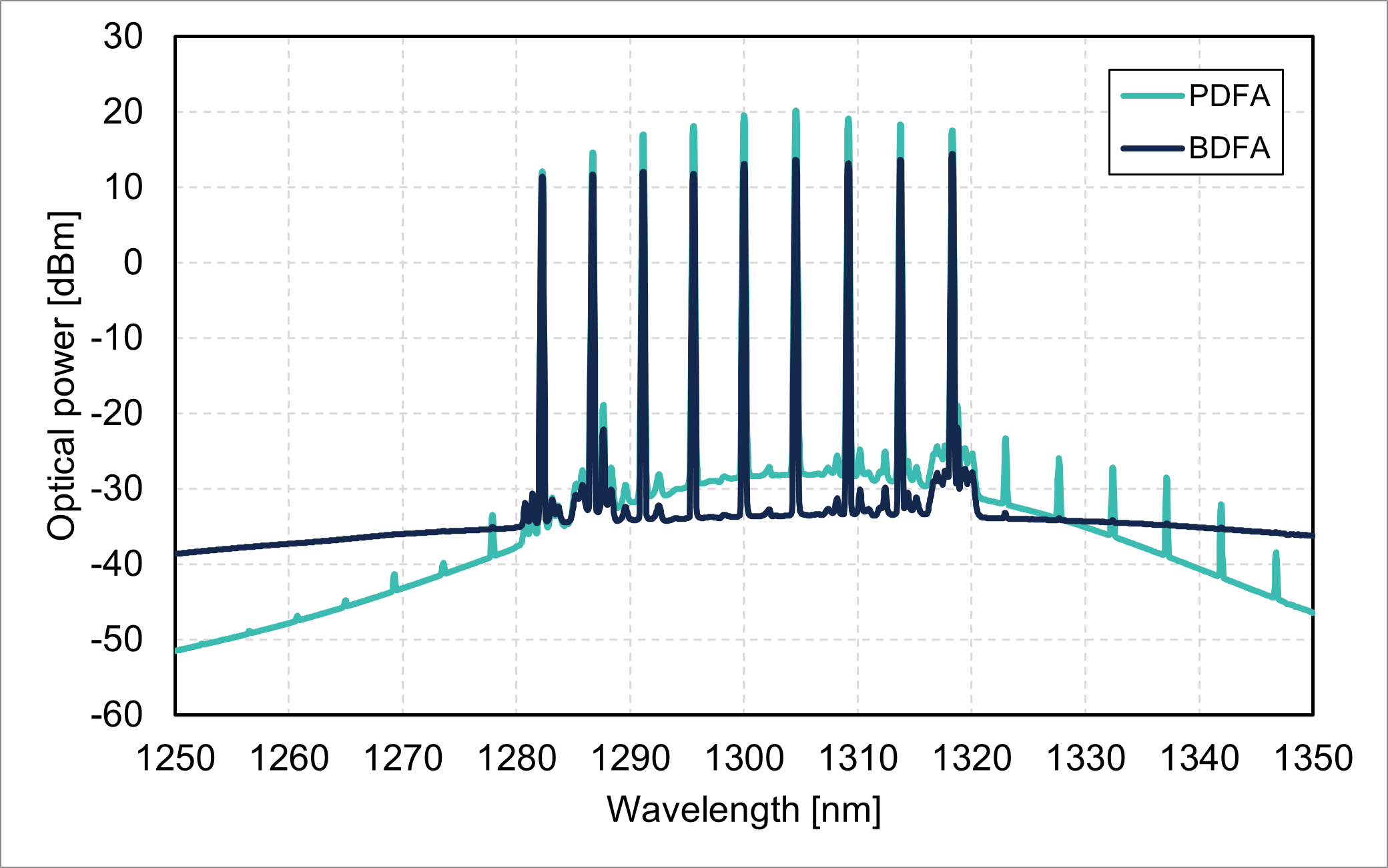
Figure 4: Output spectra from PDFA and BDFA with the 0-dBm input signal of CW-WDM (36-nm span).
It was observed that the BDFA has a higher gain than that of the PDFA for the short wavelength signals of LR8 shown in Fig.3, which indicates that the BDFA is appropriate to amplify wideband signals such as LR8 and CWDM4 transmission.
On the other hand, the output power of the PDFA is remarkable especially in the wavelength between 1285 and 1325nm, as shown in Fig.4. This result shows that the use of PDFA is preferred for LR4 and CW-WDM amplification.
Based on these results, suitable applications for PDFA and BDFA are classified as shown in the table below.

Figure 5: Appropriate applications of PDFA and BDFA for amplification of WDM signals.
While this guideline focuses only on WDM signal amplification, these products are available for a variety of non-WDM applications such as single-channel transceiver testing, multiphoton microscopy (MPM), optical coherence tomography (OCT) and laser processing.
Please feel free to contact us via the request sheet if you are interested in using our demo units for your application.